Adventures in Passive Solar Heat Mitigation

The building Lab B occupies at 12-22 North Street was built in 1979/80 as a state-of-the-art passive solar demonstration project. With R-40+ wall insulation, a large brick thermal mass bisecting the building, and large arrays of south-facing windows on both the first and second floors, 12-22 gets and stays toasty in the winter.

File:Illust passive solar d1.gif
The seasonal logic of overhangs in passive solar design.

While the front overhang helps a bit, it also gets toasty in the summer-time (particularly the southern offices), and we discovered just how toasty when the A/C unit died in the middle of July with no prospect of replacement until September. So, some hardcore kludging was in order…

To start, we immediately aimed to deploy a few portable air conditioners, but ran into to the fact that virtually all the windows are casement windows. So, the only kind of A/C that could work would be a portable one with a hose rather than a window unit, and we needed to figure out how to get the hose out with the remainder of the window sealed.

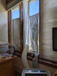
The best solution I found was a cloth adapter that attaches to either side of the window via adhesive velcro strips. In the center is a zipper with two pulls, so the exhaust tube can be zipped in and form a decent (but obviously not perfect) seal. One obvious downside is that it does not provide security, so for the window facing the street (rather than behind a fence) I ended up taking it down and closing the window at the end of each day. With the velcro, that was not a huge pain – once you have the hang of it, it’s maybe a minute to deploy, and less to break down.

I this is the hottest summer of my life GISTEMP Annual Trend 1979-2019 this is the coldest summer of the rest of your life - America's best pics and videos
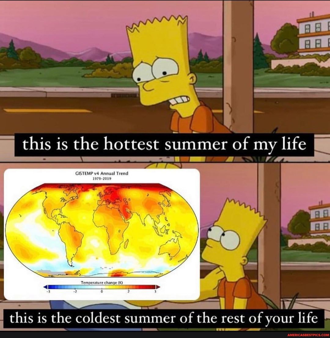
The portable A/Cs took some of the edge off, but were clearly insufficient to get and keep the building at a comfortable temperature, particularly with “Earth’s Hottest Summer on Record” heat waves rolling in. So, in addition to our machines desperately pumping heat out of the building, we needed to figure out ways to minimize the heat coming into the building (“solar gain”).

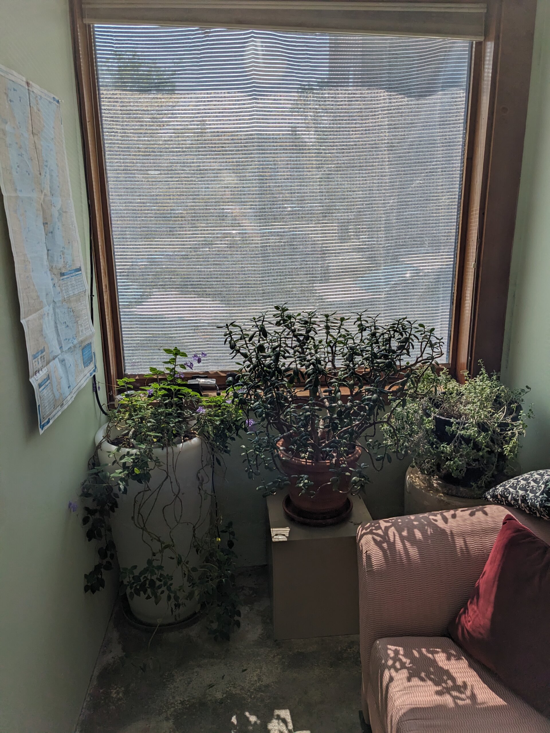
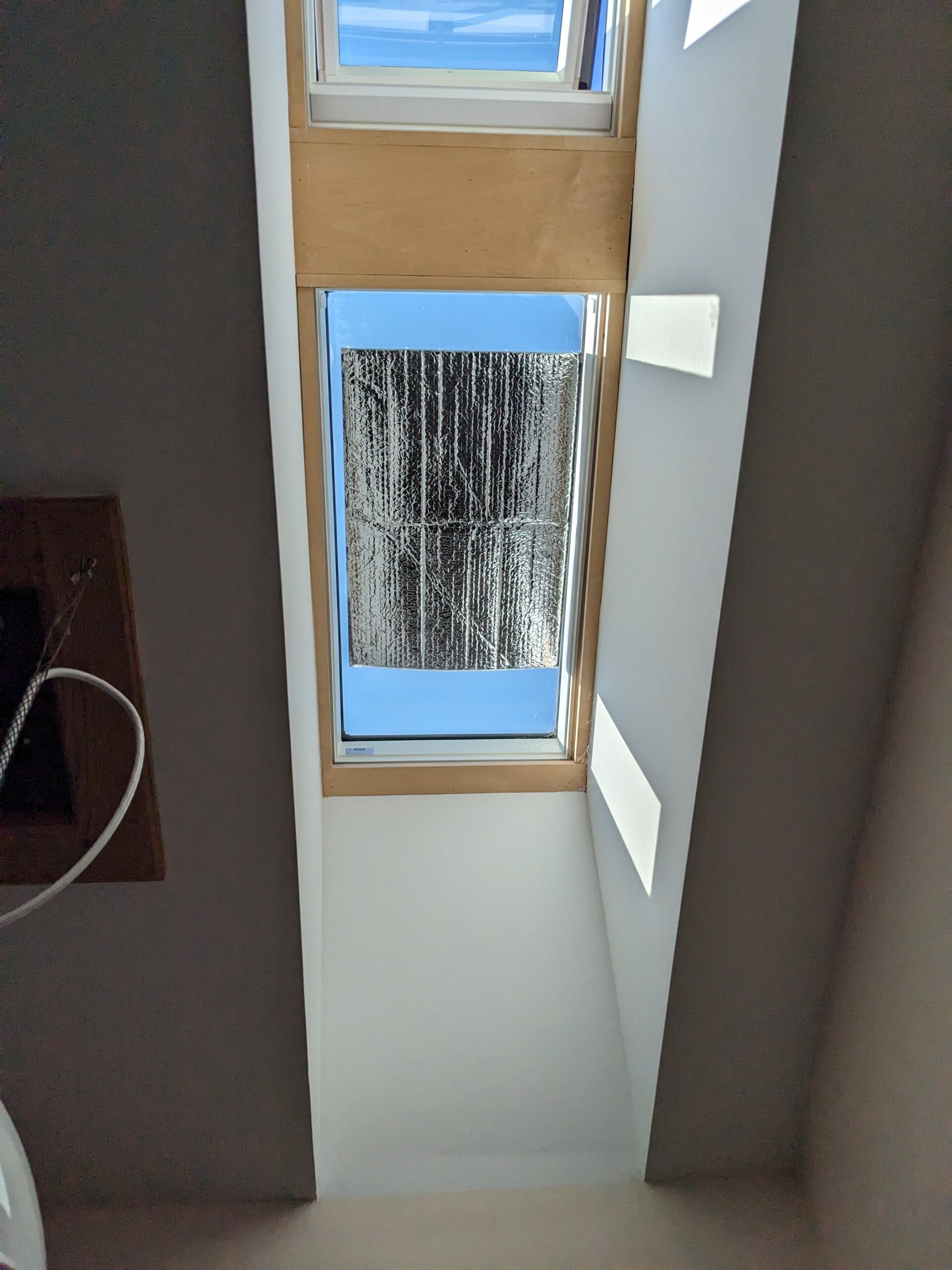
The windows were already equipped with off-white cellular blinds which insulate and reflect a bit of heat, so my first addition was mounting some reflective bubble foil insulation to the interior of some windows, starting with the skylights. Being in a hurry, I simply used some loops of painters tape to adhere them to the skylights and some windows.

This approach made a dent, but had two signficant flaws. First, no matter how reflective the material, once light passes into the building, a significant portion of the energy of the incoming light is captured as heat inside the building envelope. And said heat concentrated between the foil insulation and the window. With sufficient exposure to those high temperatures, the adhesive in the tape weakened and my sun-blocks gracefully fluttered to the floor within a matter of days.

A far superior approach is to intercept the solar heat before it enters the building envelope. The most common way of achieving this is with reflective film that is applied to the exterior of the window. However, as we didn’t want to give up the helpful solar gain in the Winter to mitigate our Summer suffering, we needed a more temporary solution that could be deployed when needed, and easily broken down and stored when not. One of the nicer options seems to be solar screens, but they were beyond both our current budget and time-frame – we required something that could arrive and be deployed quickly on a budget.

Aluminet deployedAluminet interior
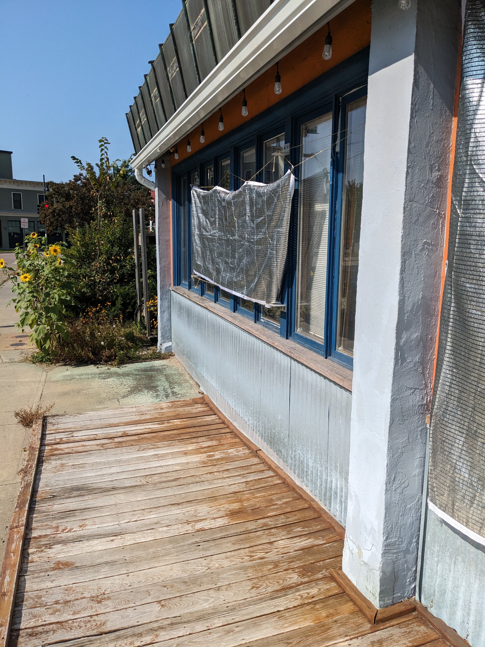
So, the first thing I decided to try was Aluminet. It’s a reflective woven material that comes in tarps, and is commonly used for shading crops in hot climates. You can order tarps that let various percentages of light through. I ordered two tarps that block 70% and let 30% through with different dimensions, and mounted them over some of the front windows. They seemed to be fairly effective, while still letting enough light through that the interior space didn’t feel gloomy. Another benefit that became apparent when I mounted a reflective solid tarp over another window to perform a similar function is aluminet’s relative resilience to high winds. When a thunder storm rolled through, the solid tarp became a kite that I had to go running after, while the holes in the aluminet meant the wind passed through and blowing away was never a problem.

Suction cup exterior shades
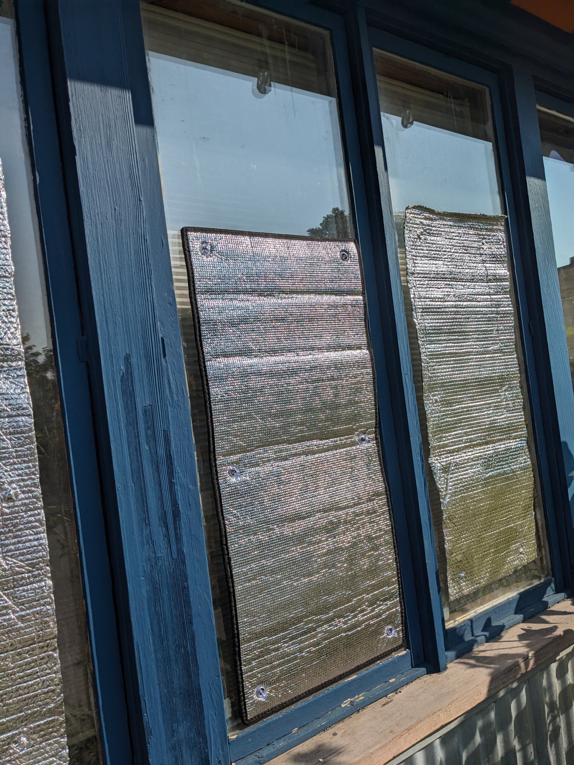
A second affordable/DIY exterior mounted solution I came across found me reusing the sheets of bubble foil insulation that had fallen from the skylights earlier. The core idea is simple: add suction cups to the corners and stick them on the window exterior. After ordering a professionally manufactured version with a few week lead-time for under $20, I scrounged up some used suction cups to make a few (less attractive) DIY versions for immediate deployment. I only made them about half of the height of the window, as the top portion tends the be shaded by the overhang, and so they would block most of the heat while still allowing natural light into the offices.

As they accumulated, the exterior interventions made a meaningful dent on the solar gain, and gave our long-suffering portable A/C units the breathing room they needed to keep the building mostly comfortable.

With the arrival of the 45 degree nights of Vermont’s Fall, the urgency of this work has begun to fade, and installation of the building’s new heat pump has begun, so the end of the crisis period is in sight. However, the motivation of avoiding an 80+ degree office ended up teaching me a lot about the dynamics of solar gain. It also provided ideas for annual interventions (such as obtaining a full complement of the professional suction cup-mounted window coverings) that will, complementing the new HVAC, allow the building to operate far more efficiently in the coming (ever hotter) Summers.

Stay Cool!

Burlington Hacker Book Club!

We’re excited to add a new event to the Lab’s roster: the BTV Hacker Book Club! The group will be meeting monthly to discuss a book drawn from a list built by Lab members, with members voting on which book from the list to read each month. While Lab members pick the books, all who have read the book are welcome to the discussions, and attendees are welcome to bring munchies and beverages to share.

Our first pick is A Hacker Manifesto by media theorist McKenzie Wark, and we’ll be gathering for the discussion on Thursday, 8/17 at 6pm in the Couch Room. For more details and updates, RSVP to the Facebook event.

We’ll be discussing setting a recurring monthly date at the August meeting, and Lab members are presently voting on the September book pick. Cyberpunk classic Neuromancer by William Gibson currently holds a narrow lead, but there are a few more days for members to weigh in…

Zero to Hero Class: Pirate Box Edition.

I’ll be teaching a class on how to setup a Pirate Box at the Generator on March 22nd. Check out more info and sign up here.

Want to carry around a world of important data, like Wikipedia, and health guides?piratebox_1
Need a way to share a bunch of files with some folks?
Come learn how to make a PirateBox a tool for sharing information in a secure offline manner!

PirateBox is a DIY anonymous offline file-sharing and communications system built with free software and inexpensive off-the-shelf hardware. Perfect for public spaces as a means of sharing interesting data and having offline discussions.piratebox12
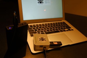
During this quick 4 hour  class students will learn how to build a Pirate Box. This class will guide students through the process of converting a plain TP-Link MR3020 and USB thumb drive into a Pirate Box.

$50 lab fee covers purchase of Pirate Box and all necessary materials (MR3020 & USB Drive).

Emergency Heat

With some inspiration from the potential snow storm last week, I endeavored to test my emergency preparedness for heating my apartment when the power is out.  I never did lose power, but the test was successful and I am happy to know that if I did lose power in the winter, I can keep warm at home.

I attached an inverter to a marine battery, then plugged in my Rinnai heater and it ran just fine.  The Rinnai does buzz a bit loudly, but that’s because the inverter does not produce a “true-sine-wave” signal.  I tested the setup with a box-fan attached to the inverter as well and it worked fine.

With the fan and the heater both running on LOW the draw was 115W. Some quick and super dirty math approximations tell me that the battery (if fully charged) will run this about 11 hours. This would be longer if the box-fan isn’t running (less power would be used).

105 Amp hours (sticker value, full charge)
105 Amp hours x 12v = 1260 watt hours (approximate average voltage)
1260 watt hours / 115 watts = ~11 hours

Of course, the inverter can be run from any 12V source.  My Honda Civic has an alternator with a faceplate rating of 70Amps.  Some quick math tells me how much power this can potentially provide.

70 Amps x 12 Vdc = 840 Wattsdc

I believe the inverter is well within the ability for the alternator to run.  So the car could potentially run the inverter as a generator as long as there is gasoline in the tank.

Check out the rest of the info and pictures at my blog.

inverter_battery
Inverter attached to battery
inverter_heater
Rinnai heater on extension cord w/ box-fan

What is a trolley? (link)

I recently found a great set of posts about what a trolley is and how they work at Nathan Vass’ website.  The short version is that a trolley is an electric bus that gets its power from overhead lines.  There are many advantages to using a bus with rubber tires over a train (can change lanes, can avoid obstacles, climb hills without wheel-spin) and many advantages to using an electric bus over a diesel bus, the main reason being torque to climb the hills of San Francisco.

Part i is here
Part ii is here

I originally became interested in the topic last year when I visited San Francisco.  There were many things I liked about the city that appealed to different interests of mine (city planning, green spaces, diverse cultures), but one of the things that stuck out to me was the infrastructure for the trolley system.  This was not something I had expected.

edit_IMG_2122

When you look up while downtown, just below the common sight of power lines at the top of the utility poles, you see what looks at first like a rats nest of electric wires.  This is especially so around intersections in the road.  But upon further examination, patterns emerge.  I noticed that the wires were running in pairs of parallel tracks, and where one track crossed another, one of the pairs would have some extra hardware.

edit_Muni_trolleybus_wires_at_Haight

I only spent a moment trying to figure out what they could be used for when one of the Muni buses (a trolley) passed me on the street.  These are quiet, exhaust-smell free giants of public transportation that I was instantly in love with.  And this post isn’t about public transportation overall, but if you need an explanation as to why it is good and how a bus can greatly reduce congestion, this GIF explains it beautifully.

tumblr_mvqe8gUMzP1qzft56o1_500

Adding More Temp Sensors

Since my previous post I have added a couple additional temperature sensors to my piHouse project.  One is an outdoor temperature sensor that I previously programmed but never installed outside, and the other is a new sensor in my bedroom.  This involved some hardware planning and effort installing because I had to run a cable through the house and outside, but once I tested the new cable run, it was relatively simple to duplicate the software for the sensors I already had.

The part of this that took the most time was pulling the cable and then soldering the connections.  The biggest problem I have is placement of the outdoor sensor.  I am having issues with direct Sunlight.

Here are some highlights, you can find the whole story here.  This time I also include some examples of the commands I use on the raspberry pi to obtain the data.


When testing my hardware connections, I use this command to ask the pi to take a reading and then display the result to the command line:

house@raspberrypi ~ $ cat /sys/bus/w1/devices/28-00000512f401/w1_slave 2>&1


show_graph_2014-10-11.cgi_[1]
ROOM TEMP lowered during day, OUT temp. sensor moved outside
Photo-Oct-14-15-20-27[1]
Three-way splice for room temp.
show_graph_2014-10-13.cgi_[1]
Added bedroom plot, outside sensor in sun

Lab B at Champlain Mini Maker Faire 2014

Laboratory B is all set up and ready to see you at Champlain Mini Maker Faire this weekend!  The event is on Sat. October 4th 10am – 5pm,  and Sun. October 5th 11am-4pm at Shelburne Farms in Shelburne Vermont.

Lab B has been at the Maker Faire since it started 3 years ago, and like last year and the year before, we’ll be teaching kids & adults how to solder! FairPoint Communications made a donation to help provide kits, and we have four kits from SparkFun in the mix this year; Weevil Eye, Big Time Watch, Simon Says & Mr. Roboto.

From our excerpt in the schedule:

“Join the folks at Laboratory B for a self-paced soldering workshop. We bring the soldering irons and the kits, you bring the desire to learn.  We will have kits from SparkFun and all the required supplies and safety gear for you to sit down and learn how to solder, and when you finish you take the kit home!  Have you soldered in the past but are not familiar with some of the newer techniques such as surface-mount soldering?  No problem!  There will be beginner kits, intermediate kits, and advanced level kits to fit all skill levels.”

pre_maker_faire_2014

Aaron’s piHouse Monitor part 2

In March I posted about using my Raspberry Pi to monitor my furnace and the temperature of my apartment.  I moved over the summer and the new apartment does not have the same type of heating that the last apartment did. So I had to make some changes.

The Pi now interfaces with a Rinnai heater, which was slightly more complicated than the furnace thermostat.

Here are some highlights, you can find the whole story here.

The new heater, a Rinnai  Energy Saver-551F
The new heater, a Rinnai Energy Saver-551F
rinnai_block_diagram
The Wiring Diagram and the Block diagram are on the inside of the front cover
Photo of “MICRO COMPUTER PCB” with relays circled
Assembling the whole thing

Aaron’s piHouse Monitor

I’ve been working on a Raspberry Pi project and got it running this weekend.  This post is about the hardware and the installation.  I will post later about how the code works.

OverviewIntroduction

I have been using microcontrollers for a long time now.  I started in college as part of the program and have never stopped.  Professionally, educationally, hobby, I’ve done projects of all types.

Recently I decided to try something with a Raspberry Pi.  It is the next step up, basically being a little computer.  This was so I could play with Linux again (it’s been years) and do something with a web browser.  These are things I don’t have experience with and have been interested in learning for some time.

The project I settled on was a monitor for the furnace in my apartment.  This monitor will measure temperature(s) and sense if the furnace is running, then log this data.  There will be a web interface that will draw graphs of the data on a daily basis.  There will also be an LCD screen on the pi so that I can see the current data without needing a web browser.

Part 1: Hardware

The first step was to make sure I could sense whether the furnace was running.  My furnace is controlled by a thermostat.  A thermostat is a temperature controlled mechanical switch.  Mine looks like this (The wire hanging down was added later):

Photo Mar 02, 17 01 40 edit


I needed to open this up to see how it worked.  So, I pulled off the ring on the front and exposed 3 screws holding it to the wall.  I took out the screws and pulled the switch off the wall.  I was left with a mounting plate that included a set of screw terminals with a 2 conductor wire attached.  This is the wire running to the furnace in the basement that controls the furnace.

Photo Mar 02, 17 02 01 - Edit thermostat


The screw terminals were labeled as RH and W.  I took out my mult-meter and started doing some measuring.

Open (Furnace off): RH -> W, 25.8 VAC
Closed (Furnace on): RH -> W, 0 VAC @ 95mA

This means that I need to monitor the voltage across terminals RH and W.  If voltage is present, the furnace should be off.  The 95mA is mostly unimportant because the thermostat is going to stay in place.  I just need to make sure the pi doesn’t draw so much current that it turns on the furnace on it’s own.  I drew up the below circuit to accomplish this using a rectifier circuit and an opto-isolator fed into GPIO24.

furnace 

In this circuit, when the thermostat is open, the 10K resistor attached to the terminals limits the current feeding the 4 diodes, which function as a bridge-rectifier.  This rectified AC then drives the LED of the opto-isolator.  When the LED is lit, is turns on the transistor, shorting GPIO24 to GND with a 1uF cap for smoothing because its an AC signal.  When the thermostat is closed, there is no current driving the opto-isolator and GPIO24 is pulled up to to 3.3V by a 100K resistor.

With the furnace monitoring designed, I had to decide on a temperature sensor.  Unfortunately, the raspberry pi doesn’t have any built-in analog inputs.  This was a little disappointing because it’s a standard feature on most microcontrollers I have used, however this is a computer.  After a little research, I settled on a sensor that uses the Dallas 1-wire protocol.  This is a serial bus that is similar to I2C.  I liked it becuase there is pi support and since it is a bus, it is expandable (multiple sensors) without using more inputs.  I found some DS18B20 1-wire Temperature Sensor ICs in a probe package with wire attached on Amazon, a bought a few.

Following the datasheet recommendations, I wired up the temp sensor like this:

1-wire 

The last piece for this was an LCD screen.  I did some research and picked a product from Adafruit that has a 16X2 RGB LCD Screen and 5 buttons on a “shield” style board that plugs into the GPIO header on the pi.  I ordered one and when it came in, I soldered it together.

After much programming (That will be a future post), I had all the parts working.  So it was time to put the unit together.  I plugged the LCD screen into the pi, then soldered some wires to the backside of the header-pins on the LCD shield.  The other ends of the wires go to some proto-board where I built the schematics pictured above.  I then added a 2-conductor wire in parallel to the thermostat and connected the other end to the pi’s “furnace” input.  I wired up the Temperature sensor.  I mounted it all to a bookshelf and fired it up.

thermostat_pi proto-board temp-sensor pi_installed_edit

show_graph


Soldering Workshop:Fix a phone edition!

Potential new member Charles stopped by the Laboratory to use the soldering station. Seems he tried an external antenna on his Samsung phone and the connector broke on him. This external antenna connector bypasses the internal antenna, so when it broke the phone could no longer use the 4G LTE antenna! Thus Charles was stuck with only 1x service (teh suck!). Charles used the Labs microelectronics station to desolder the broken connector. He then bridged the circuit with a bit of wire. Service went from 1x to 4G with 3 bars with this simple fix.

2013-09-05 18.36.30
After the MCA connector was removed.
Click to expand.
2013-09-05 19.21.12
After the connector was bridged with a bit of wire.
Click to expand.