I’ve been working on a Raspberry Pi project and got it running this weekend. This post is about the hardware and the installation. I will post later about how the code works.
 Introduction
I have been using microcontrollers for a long time now. I started in college as part of the program and have never stopped. Professionally, educationally, hobby, I’ve done projects of all types.
Recently I decided to try something with a Raspberry Pi. It is the next step up, basically being a little computer. This was so I could play with Linux again (it’s been years) and do something with a web browser. These are things I don’t have experience with and have been interested in learning for some time.
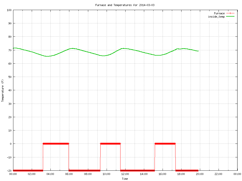
The project I settled on was a monitor for the furnace in my apartment. This monitor will measure temperature(s) and sense if the furnace is running, then log this data. There will be a web interface that will draw graphs of the data on a daily basis. There will also be an LCD screen on the pi so that I can see the current data without needing a web browser.
Part 1: Hardware
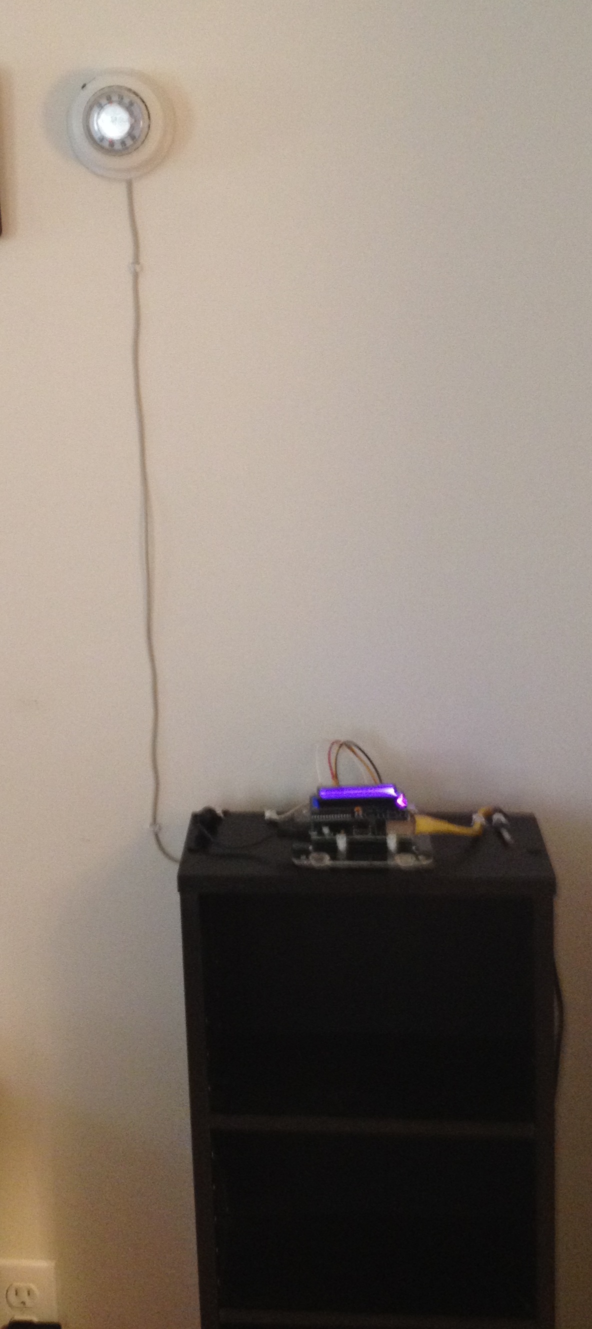
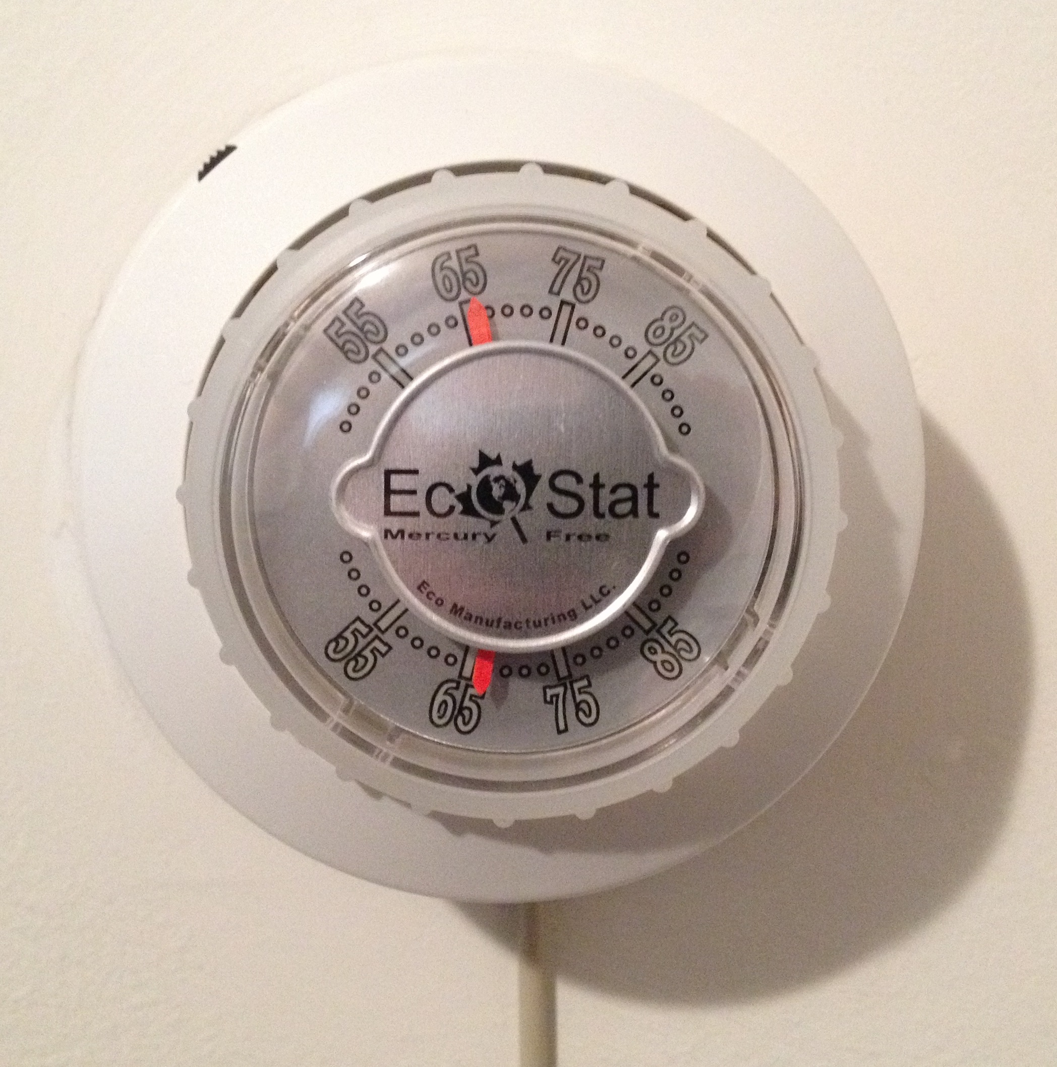
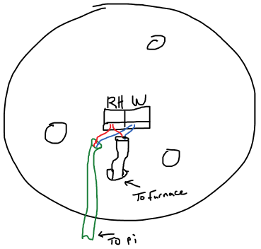
The first step was to make sure I could sense whether the furnace was running. My furnace is controlled by a thermostat. A thermostat is a temperature controlled mechanical switch. Mine looks like this (The wire hanging down was added later):
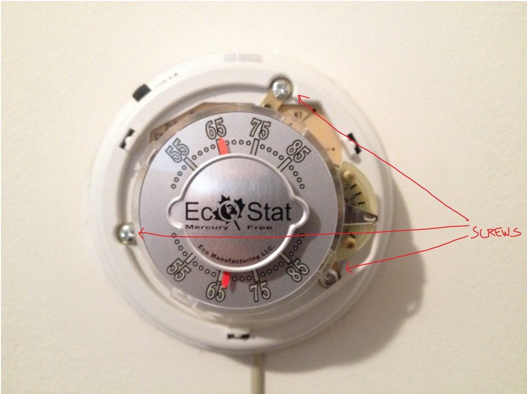
I needed to open this up to see how it worked. So, I pulled off the ring on the front and exposed 3 screws holding it to the wall. I took out the screws and pulled the switch off the wall. I was left with a mounting plate that included a set of screw terminals with a 2 conductor wire attached. This is the wire running to the furnace in the basement that controls the furnace.
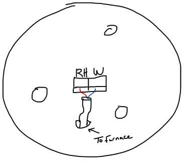
The screw terminals were labeled as RH and W. I took out my mult-meter and started doing some measuring.
Open (Furnace off): RH -> W, 25.8 VAC
Closed (Furnace on): RH -> W, 0 VAC @ 95mA
This means that I need to monitor the voltage across terminals RH and W. If voltage is present, the furnace should be off. The 95mA is mostly unimportant because the thermostat is going to stay in place. I just need to make sure the pi doesn’t draw so much current that it turns on the furnace on it’s own. I drew up the below circuit to accomplish this using a rectifier circuit and an opto-isolator fed into GPIO24.
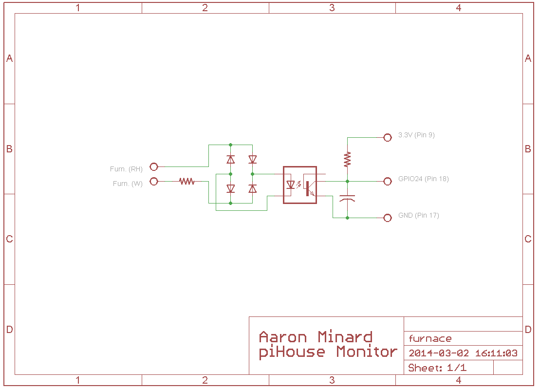
In this circuit, when the thermostat is open, the 10K resistor attached to the terminals limits the current feeding the 4 diodes, which function as a bridge-rectifier. This rectified AC then drives the LED of the opto-isolator. When the LED is lit, is turns on the transistor, shorting GPIO24 to GND with a 1uF cap for smoothing because its an AC signal. When the thermostat is closed, there is no current driving the opto-isolator and GPIO24 is pulled up to to 3.3V by a 100K resistor.
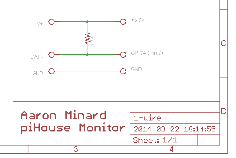
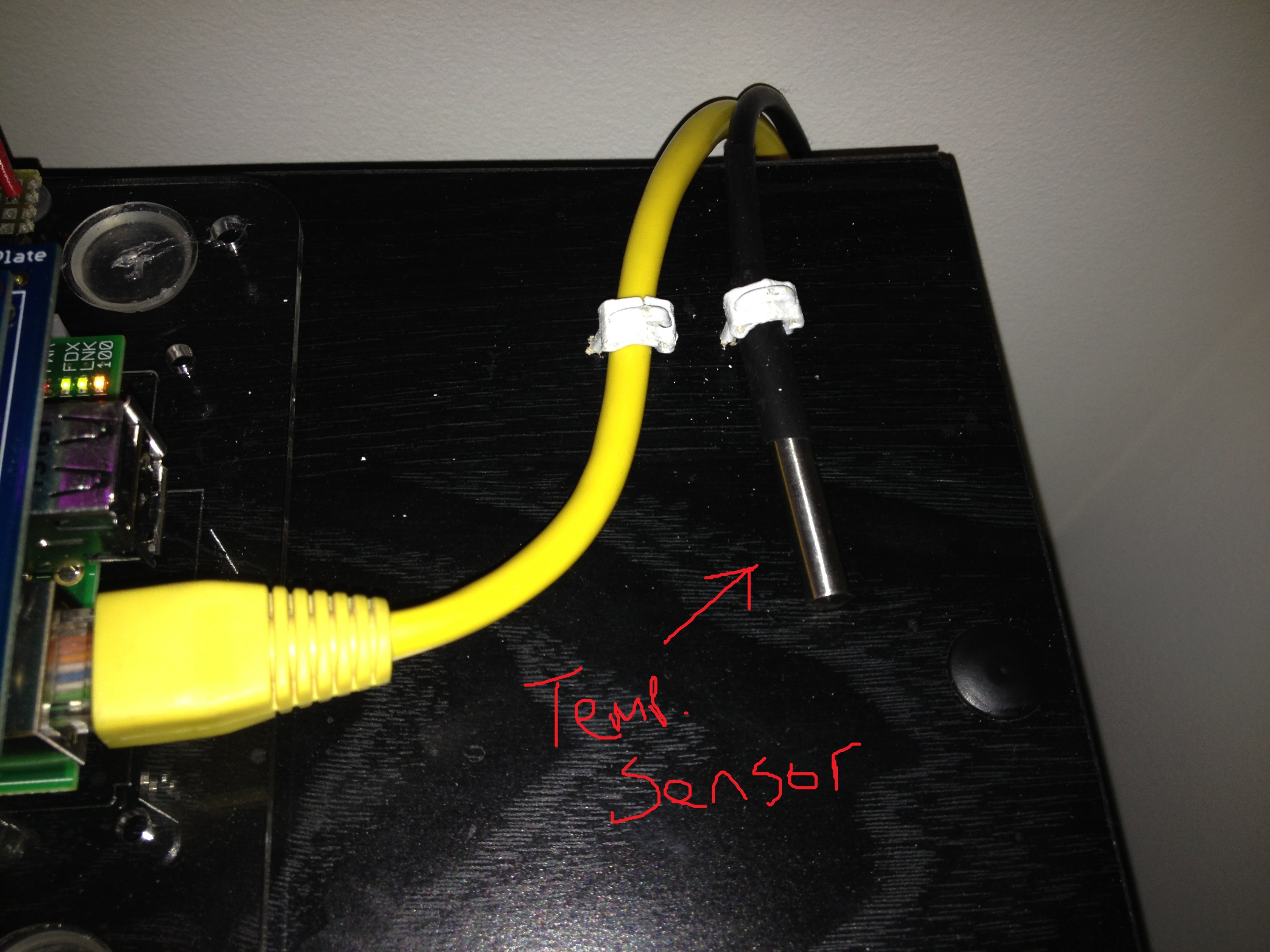
With the furnace monitoring designed, I had to decide on a temperature sensor. Unfortunately, the raspberry pi doesn’t have any built-in analog inputs. This was a little disappointing because it’s a standard feature on most microcontrollers I have used, however this is a computer. After a little research, I settled on a sensor that uses the Dallas 1-wire protocol. This is a serial bus that is similar to I2C. I liked it becuase there is pi support and since it is a bus, it is expandable (multiple sensors) without using more inputs. I found some DS18B20 1-wire Temperature Sensor ICs in a probe package with wire attached on Amazon, a bought a few.
Following the datasheet recommendations, I wired up the temp sensor like this:
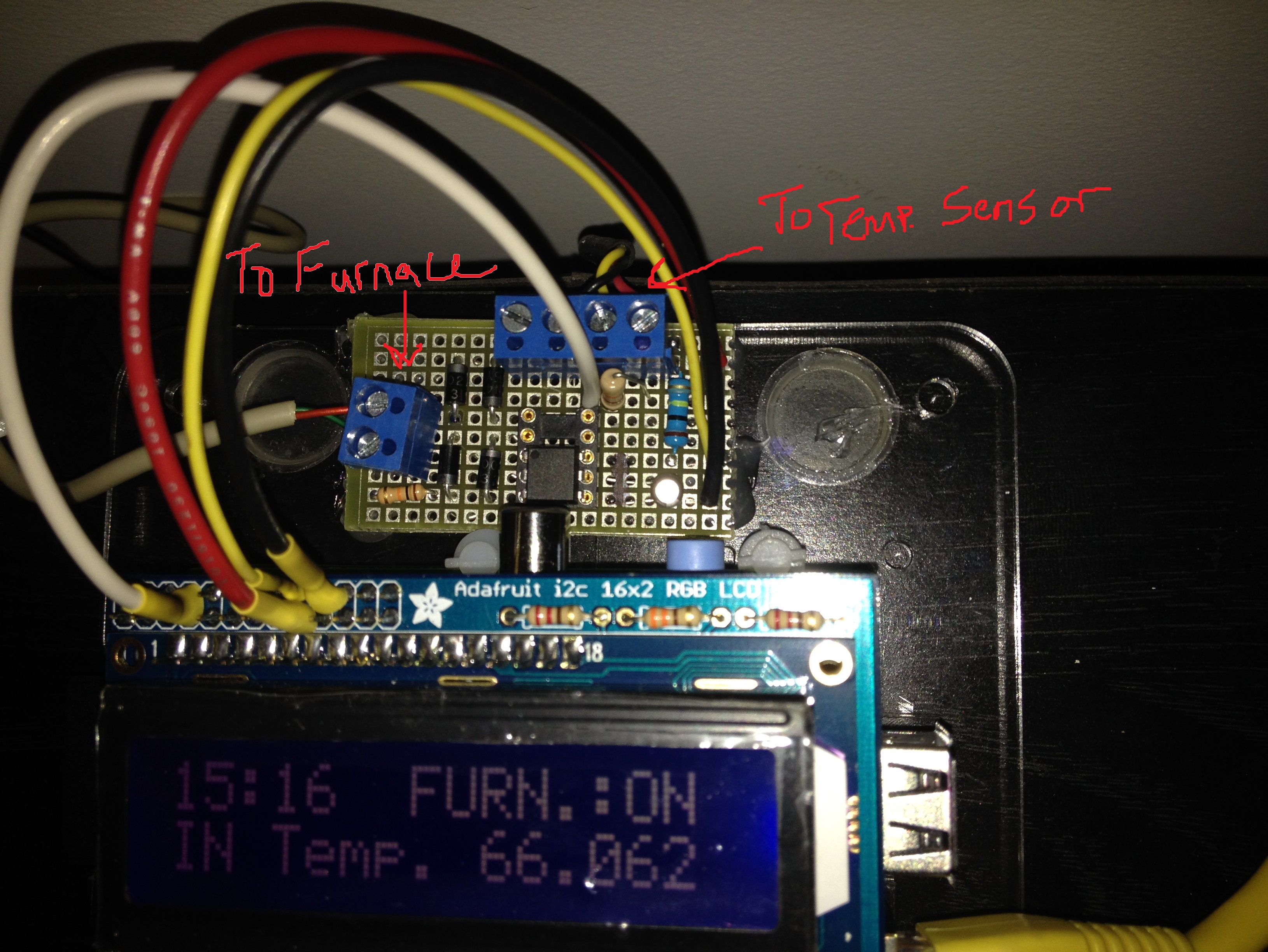
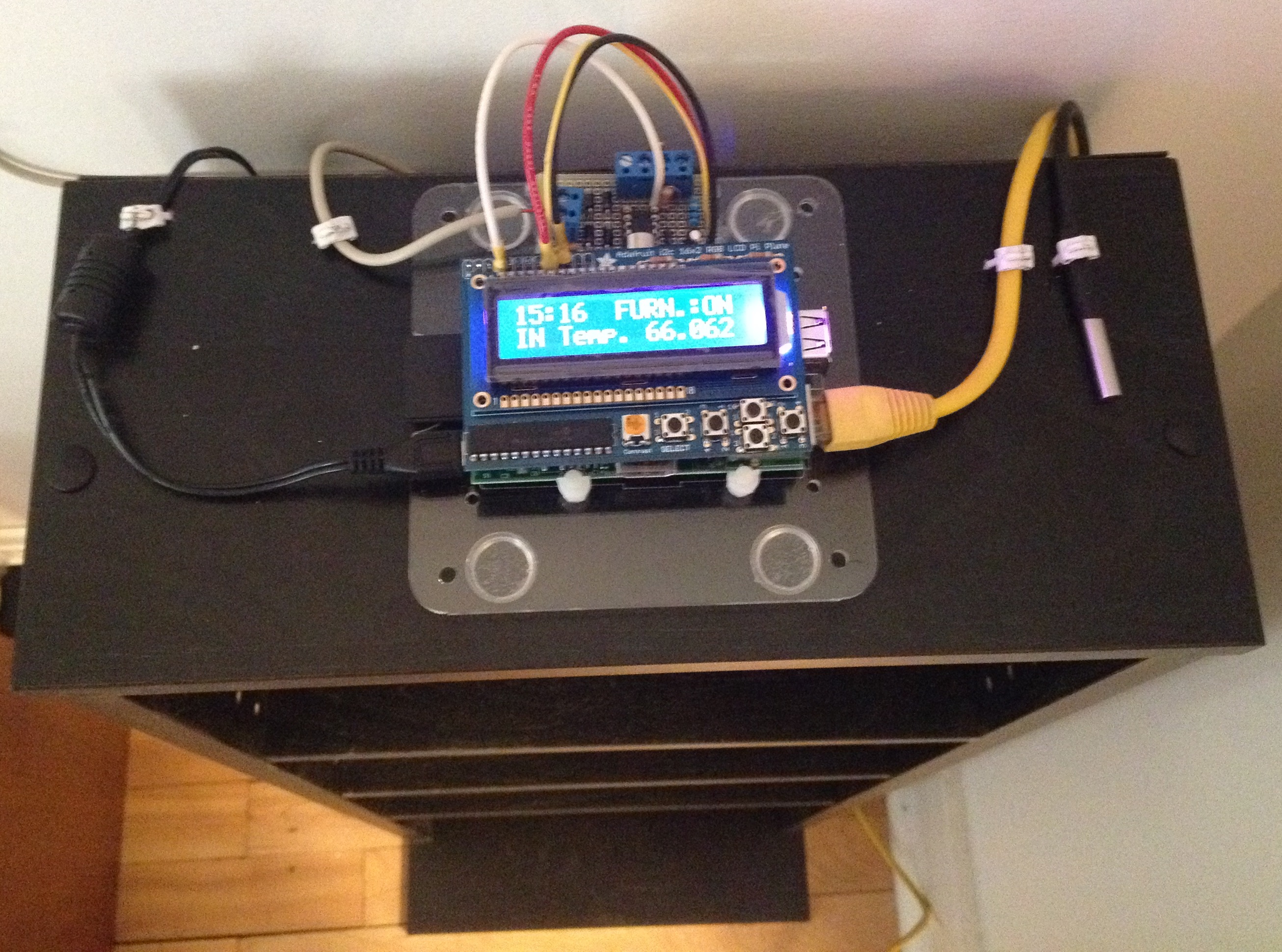
The last piece for this was an LCD screen. I did some research and picked a product from Adafruit that has a 16X2 RGB LCD Screen and 5 buttons on a “shield” style board that plugs into the GPIO header on the pi. I ordered one and when it came in, I soldered it together.
After much programming (That will be a future post), I had all the parts working. So it was time to put the unit together. I plugged the LCD screen into the pi, then soldered some wires to the backside of the header-pins on the LCD shield. The other ends of the wires go to some proto-board where I built the schematics pictured above. I then added a 2-conductor wire in parallel to the thermostat and connected the other end to the pi’s “furnace” input. I wired up the Temperature sensor. I mounted it all to a bookshelf and fired it up.
Awesome. Then you can compare your fuel bill to your use and figure out if you’re being overcharged.
This is actually slightly tricky. I can get an idea of each month for time the furnace was running and cost (minutes/dollar), but this isn’t the whole picture. The thermostat isn’t the only time the heater runs because it is a combined hot water and furnace unit. Also, this isn’t how the gas company meters and charges me anyway, they do by volume. So, if the bill was double all of a sudden (like in January, brrrrr) I can see if the furnace ran double. But I can’t tell if they are charging me correct in the first place.
tl;dr – I need a flow meter like the gas company has to see if they overcharge me.
But nice thinking! That is the eventual goal… meter the furnace directly.
Outdoor temperature would be another data point to pick up and compare to the indoor temp over time. You could figure out the heating demand for your building. The furnace frequency will go up with the delta T. It might even be possible to figure out the hot water portion by comparing furnace demand when hot water is not used … then subtracting out from daily load. Heating fuel companies use heating-degree-days and the first few fill-ups to establish a baseline for the building. …. thereafter they know the fuel level in your tank without sensors to reasonably estimate the next delivery date.
I just setup a second temp. sensor this past weekend. The delta T is exactly what I am looking for. I am also moving and the new place has a Rinnai heater, which will add some complications. I hope to be able to sense each heating section (there are 3) and then I can log the various “levels” of heat output (1, 2 or 3). This is going to be coupled with the outside, and maybe each room after that. Also, the new place is electric hot water so the natural gas consumption will be just the heater. I’m looking forward to it.
Awesome Job!
I’ve heard some horror stories of heaters being stuck on due to valve issues – any thoughts on creating an sms alert or something similar? These are the kind of features that make me want to keep working on my own smartouse ideas.
I am building a system to monitor our Heat Pump vs Supplemental Heat on-time. I couldn’t get your optoisolator circuit working as shown, I removed the 1uF filter cap on the out put and instead installed a 100uF cap to filter the output of the rectifier. Worked great…which lead to me removing he full-wave bridge rectifier and replacing it with a half wave rectifier (a single diode feeding the optoisolator). This required upping the cap to a 470uF cap to filter the poor DC feeding the optoisolator. So far I have solid reliable results. I will try to share schematics when I am all done and draw them up.
Eventually I may make a full Pi thermostat with this project.