Emergency Heat

With some inspiration from the potential snow storm last week, I endeavored to test my emergency preparedness for heating my apartment when the power is out.  I never did lose power, but the test was successful and I am happy to know that if I did lose power in the winter, I can keep warm at home.

I attached an inverter to a marine battery, then plugged in my Rinnai heater and it ran just fine.  The Rinnai does buzz a bit loudly, but that’s because the inverter does not produce a “true-sine-wave” signal.  I tested the setup with a box-fan attached to the inverter as well and it worked fine.

With the fan and the heater both running on LOW the draw was 115W. Some quick and super dirty math approximations tell me that the battery (if fully charged) will run this about 11 hours. This would be longer if the box-fan isn’t running (less power would be used).

105 Amp hours (sticker value, full charge)
105 Amp hours x 12v = 1260 watt hours (approximate average voltage)
1260 watt hours / 115 watts = ~11 hours

Of course, the inverter can be run from any 12V source.  My Honda Civic has an alternator with a faceplate rating of 70Amps.  Some quick math tells me how much power this can potentially provide.

70 Amps x 12 Vdc = 840 Wattsdc

I believe the inverter is well within the ability for the alternator to run.  So the car could potentially run the inverter as a generator as long as there is gasoline in the tank.

Check out the rest of the info and pictures at my blog.

inverter_battery
Inverter attached to battery
inverter_heater
Rinnai heater on extension cord w/ box-fan

What is a trolley? (link)

I recently found a great set of posts about what a trolley is and how they work at Nathan Vass’ website.  The short version is that a trolley is an electric bus that gets its power from overhead lines.  There are many advantages to using a bus with rubber tires over a train (can change lanes, can avoid obstacles, climb hills without wheel-spin) and many advantages to using an electric bus over a diesel bus, the main reason being torque to climb the hills of San Francisco.

Part i is here
Part ii is here

I originally became interested in the topic last year when I visited San Francisco.  There were many things I liked about the city that appealed to different interests of mine (city planning, green spaces, diverse cultures), but one of the things that stuck out to me was the infrastructure for the trolley system.  This was not something I had expected.

edit_IMG_2122

When you look up while downtown, just below the common sight of power lines at the top of the utility poles, you see what looks at first like a rats nest of electric wires.  This is especially so around intersections in the road.  But upon further examination, patterns emerge.  I noticed that the wires were running in pairs of parallel tracks, and where one track crossed another, one of the pairs would have some extra hardware.

edit_Muni_trolleybus_wires_at_Haight

I only spent a moment trying to figure out what they could be used for when one of the Muni buses (a trolley) passed me on the street.  These are quiet, exhaust-smell free giants of public transportation that I was instantly in love with.  And this post isn’t about public transportation overall, but if you need an explanation as to why it is good and how a bus can greatly reduce congestion, this GIF explains it beautifully.

tumblr_mvqe8gUMzP1qzft56o1_500

Adding More Temp Sensors

Since my previous post I have added a couple additional temperature sensors to my piHouse project.  One is an outdoor temperature sensor that I previously programmed but never installed outside, and the other is a new sensor in my bedroom.  This involved some hardware planning and effort installing because I had to run a cable through the house and outside, but once I tested the new cable run, it was relatively simple to duplicate the software for the sensors I already had.

The part of this that took the most time was pulling the cable and then soldering the connections.  The biggest problem I have is placement of the outdoor sensor.  I am having issues with direct Sunlight.

Here are some highlights, you can find the whole story here.  This time I also include some examples of the commands I use on the raspberry pi to obtain the data.


When testing my hardware connections, I use this command to ask the pi to take a reading and then display the result to the command line:

house@raspberrypi ~ $ cat /sys/bus/w1/devices/28-00000512f401/w1_slave 2>&1


show_graph_2014-10-11.cgi_[1]
ROOM TEMP lowered during day, OUT temp. sensor moved outside
Photo-Oct-14-15-20-27[1]
Three-way splice for room temp.
show_graph_2014-10-13.cgi_[1]
Added bedroom plot, outside sensor in sun

Champlain Mini Maker Faire Roundup 2014

The Laboratory B crew had a great time at this year’s two day  Champlain Mini Maker Faire! This year we had additional support from FairPoint Communications to allow us to teach kids & adults how to solder.  We had really impressive students this year, many of whom have seen us before at the previous events.  Many people were coming back for their second or even third time.  Good work everybody and thanks for coming out to see us!  As usual, if you had trouble with your kit or ran out of time please feel free to swing by the Lab, but let us know your coming ([email protected]) Awesome!

Charley helping out as usual!
Charley helping brothers that don’t need much help. Good work guys!

Lab B at Champlain Mini Maker Faire 2014

Laboratory B is all set up and ready to see you at Champlain Mini Maker Faire this weekend!  The event is on Sat. October 4th 10am – 5pm,  and Sun. October 5th 11am-4pm at Shelburne Farms in Shelburne Vermont.

Lab B has been at the Maker Faire since it started 3 years ago, and like last year and the year before, we’ll be teaching kids & adults how to solder! FairPoint Communications made a donation to help provide kits, and we have four kits from SparkFun in the mix this year; Weevil Eye, Big Time Watch, Simon Says & Mr. Roboto.

From our excerpt in the schedule:

“Join the folks at Laboratory B for a self-paced soldering workshop. We bring the soldering irons and the kits, you bring the desire to learn.  We will have kits from SparkFun and all the required supplies and safety gear for you to sit down and learn how to solder, and when you finish you take the kit home!  Have you soldered in the past but are not familiar with some of the newer techniques such as surface-mount soldering?  No problem!  There will be beginner kits, intermediate kits, and advanced level kits to fit all skill levels.”

pre_maker_faire_2014

Aaron’s piHouse Monitor part 2

In March I posted about using my Raspberry Pi to monitor my furnace and the temperature of my apartment.  I moved over the summer and the new apartment does not have the same type of heating that the last apartment did. So I had to make some changes.

The Pi now interfaces with a Rinnai heater, which was slightly more complicated than the furnace thermostat.

Here are some highlights, you can find the whole story here.

The new heater, a Rinnai  Energy Saver-551F
The new heater, a Rinnai Energy Saver-551F
rinnai_block_diagram
The Wiring Diagram and the Block diagram are on the inside of the front cover
Photo of “MICRO COMPUTER PCB” with relays circled
Assembling the whole thing

Aaron’s piHouse Monitor

I’ve been working on a Raspberry Pi project and got it running this weekend.  This post is about the hardware and the installation.  I will post later about how the code works.

OverviewIntroduction

I have been using microcontrollers for a long time now.  I started in college as part of the program and have never stopped.  Professionally, educationally, hobby, I’ve done projects of all types.

Recently I decided to try something with a Raspberry Pi.  It is the next step up, basically being a little computer.  This was so I could play with Linux again (it’s been years) and do something with a web browser.  These are things I don’t have experience with and have been interested in learning for some time.

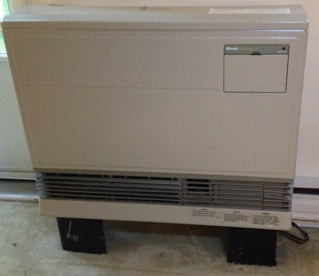
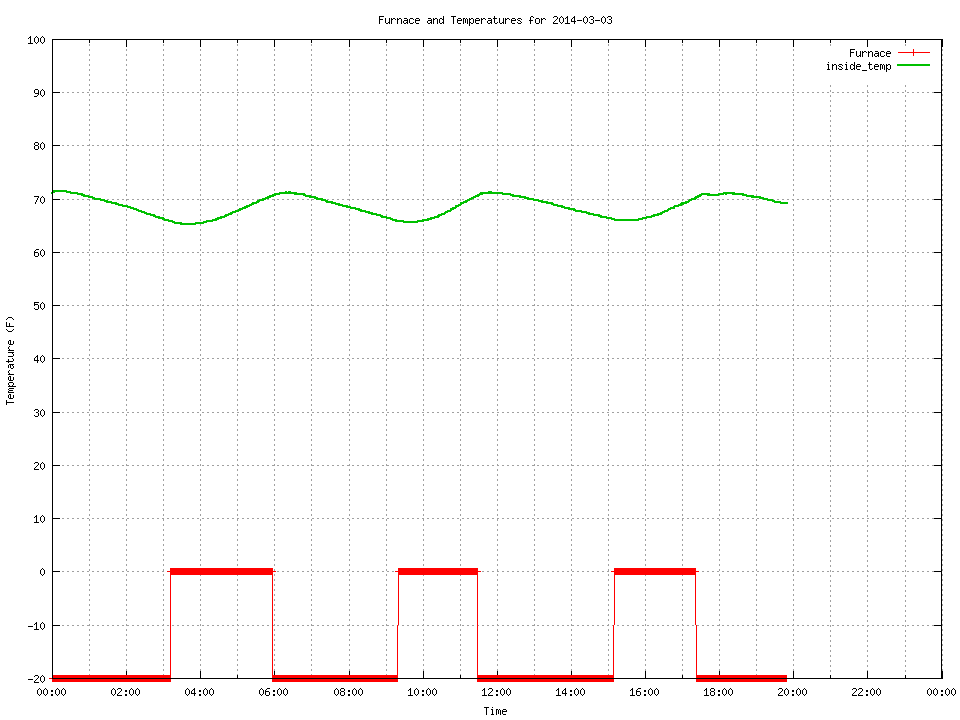
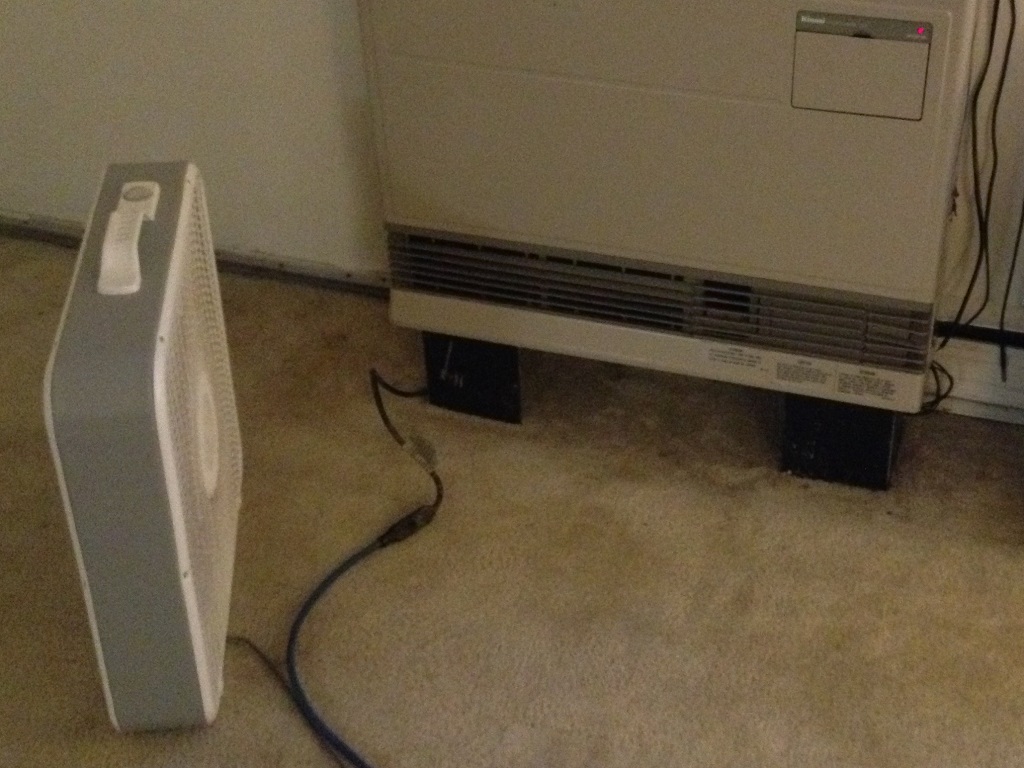
The project I settled on was a monitor for the furnace in my apartment.  This monitor will measure temperature(s) and sense if the furnace is running, then log this data.  There will be a web interface that will draw graphs of the data on a daily basis.  There will also be an LCD screen on the pi so that I can see the current data without needing a web browser.

Part 1: Hardware

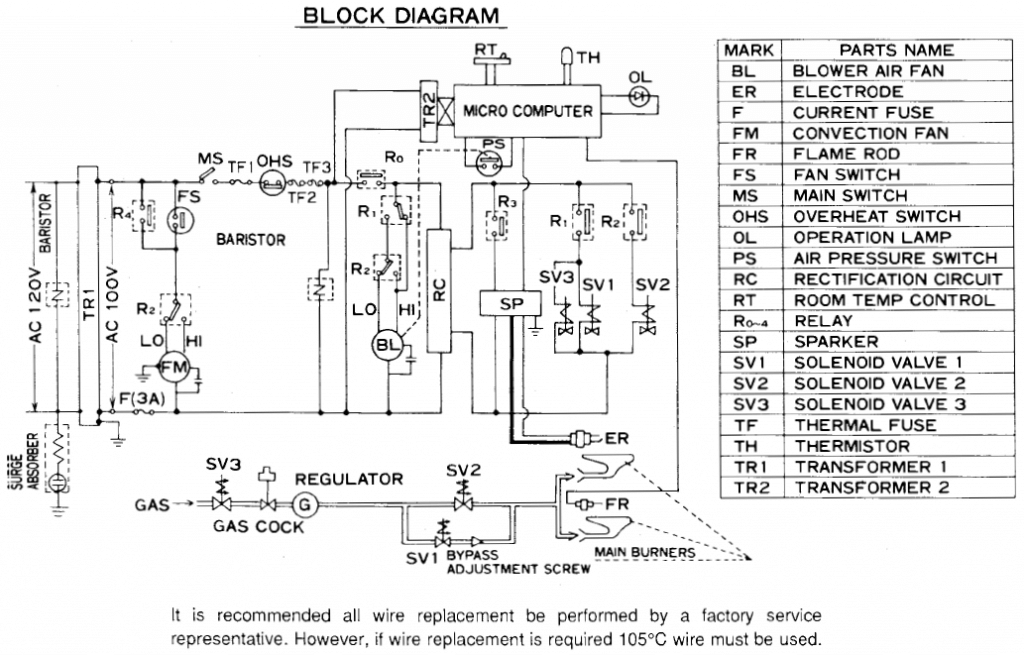
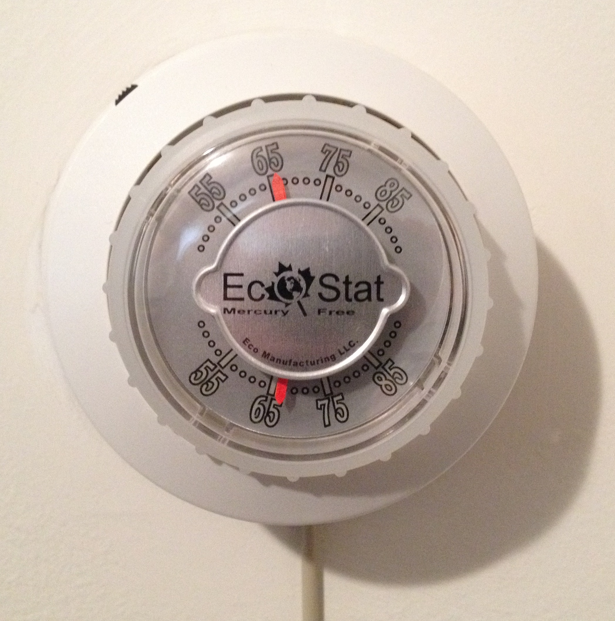
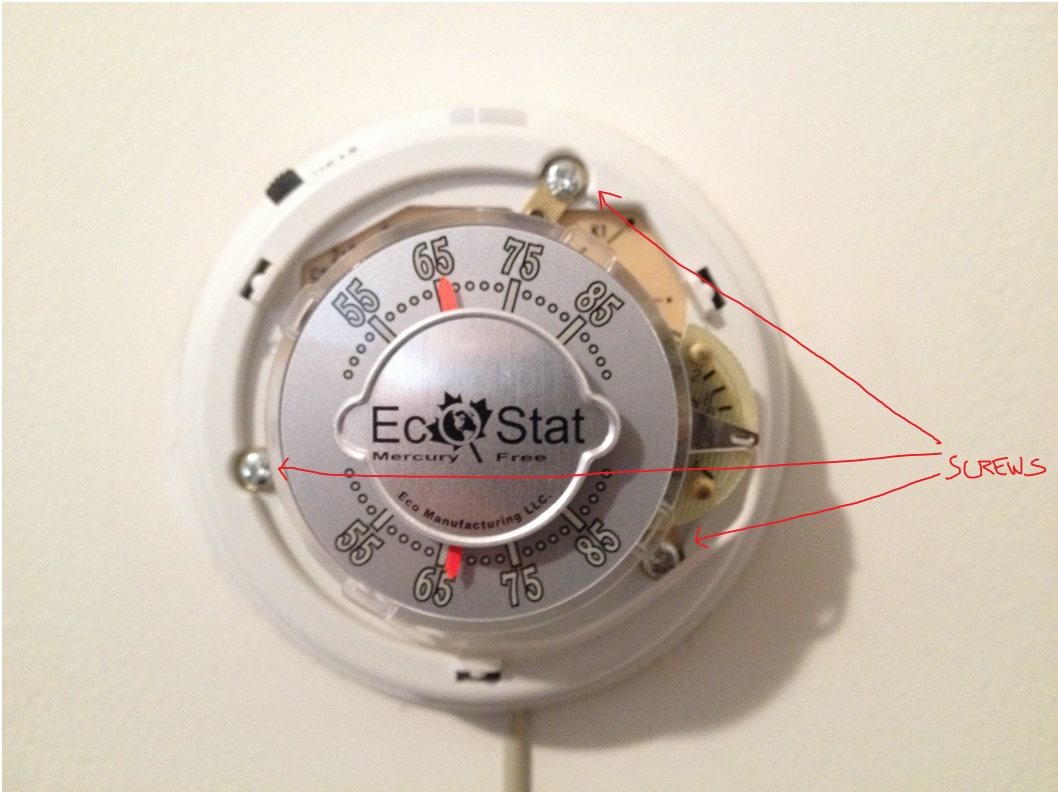
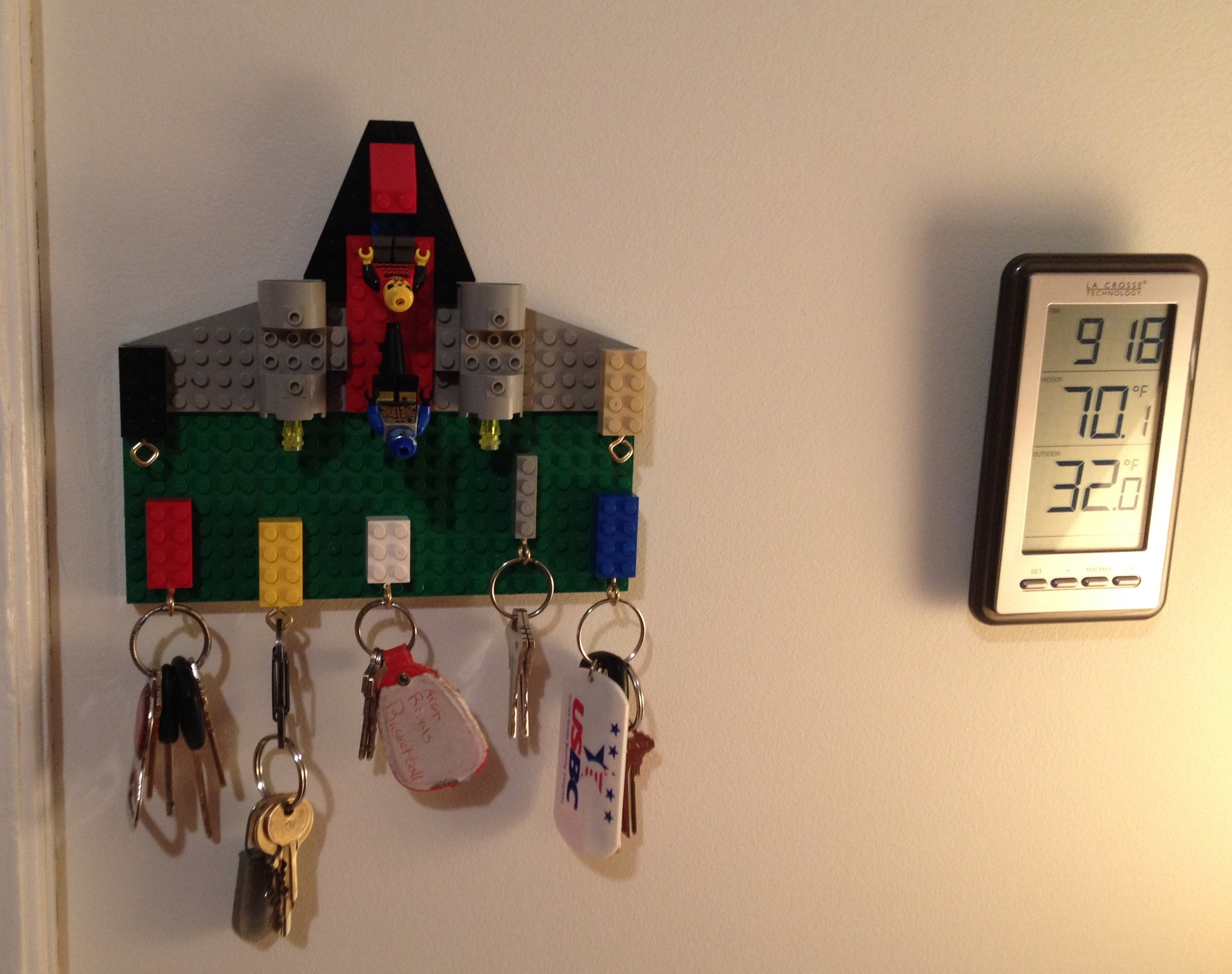
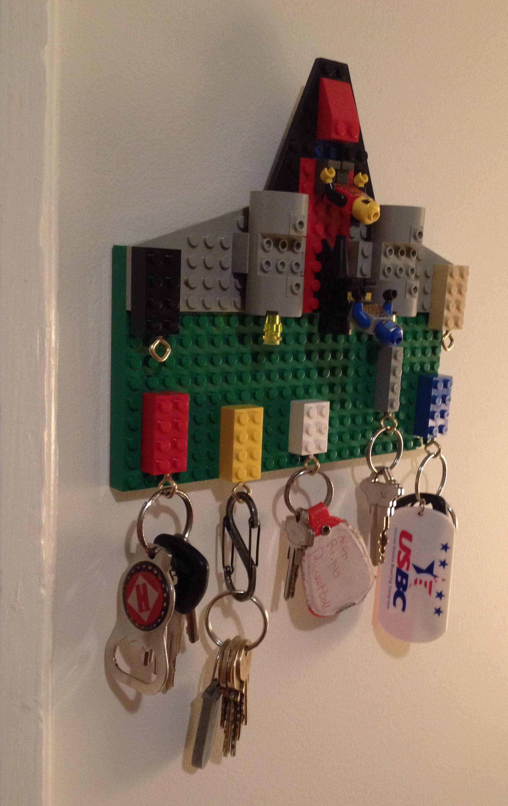
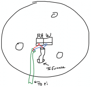
The first step was to make sure I could sense whether the furnace was running.  My furnace is controlled by a thermostat.  A thermostat is a temperature controlled mechanical switch.  Mine looks like this (The wire hanging down was added later):

Photo Mar 02, 17 01 40 edit


I needed to open this up to see how it worked.  So, I pulled off the ring on the front and exposed 3 screws holding it to the wall.  I took out the screws and pulled the switch off the wall.  I was left with a mounting plate that included a set of screw terminals with a 2 conductor wire attached.  This is the wire running to the furnace in the basement that controls the furnace.

Photo Mar 02, 17 02 01 - Edit thermostat


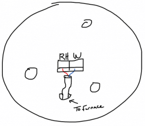
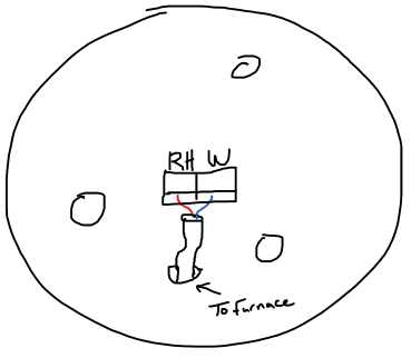
The screw terminals were labeled as RH and W.  I took out my mult-meter and started doing some measuring.

Open (Furnace off): RH -> W, 25.8 VAC
Closed (Furnace on): RH -> W, 0 VAC @ 95mA

This means that I need to monitor the voltage across terminals RH and W.  If voltage is present, the furnace should be off.  The 95mA is mostly unimportant because the thermostat is going to stay in place.  I just need to make sure the pi doesn’t draw so much current that it turns on the furnace on it’s own.  I drew up the below circuit to accomplish this using a rectifier circuit and an opto-isolator fed into GPIO24.

furnace 

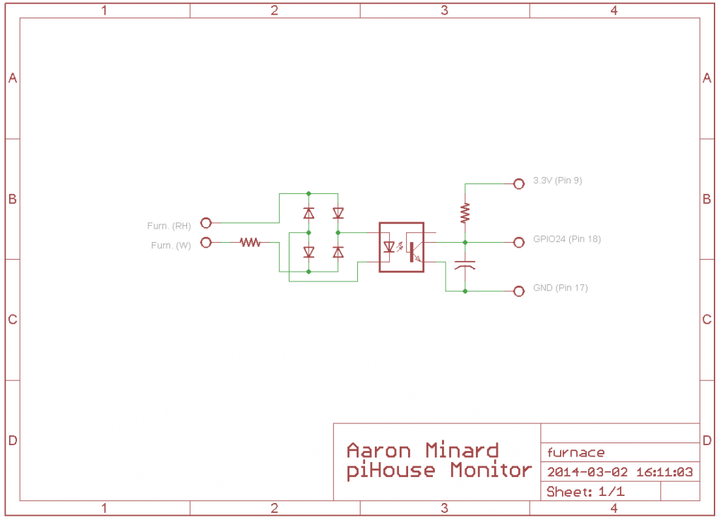
In this circuit, when the thermostat is open, the 10K resistor attached to the terminals limits the current feeding the 4 diodes, which function as a bridge-rectifier.  This rectified AC then drives the LED of the opto-isolator.  When the LED is lit, is turns on the transistor, shorting GPIO24 to GND with a 1uF cap for smoothing because its an AC signal.  When the thermostat is closed, there is no current driving the opto-isolator and GPIO24 is pulled up to to 3.3V by a 100K resistor.

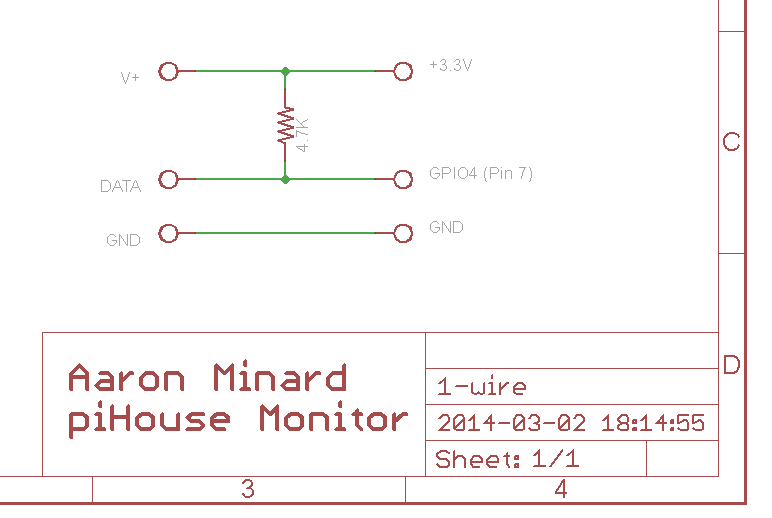
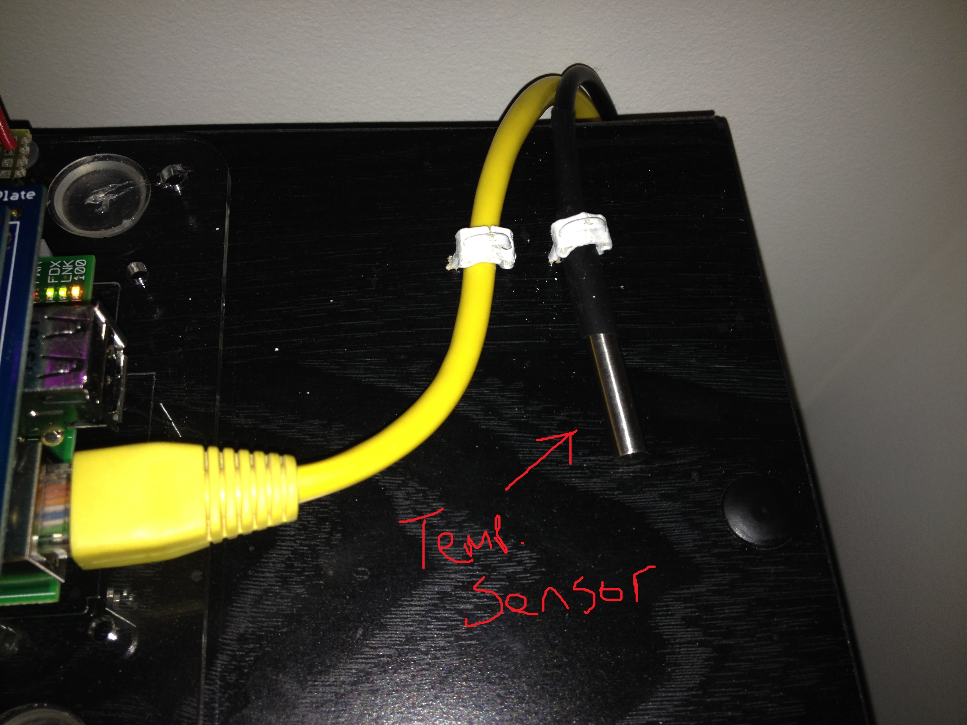
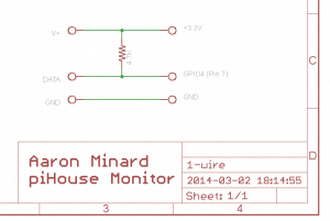
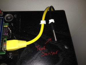
With the furnace monitoring designed, I had to decide on a temperature sensor.  Unfortunately, the raspberry pi doesn’t have any built-in analog inputs.  This was a little disappointing because it’s a standard feature on most microcontrollers I have used, however this is a computer.  After a little research, I settled on a sensor that uses the Dallas 1-wire protocol.  This is a serial bus that is similar to I2C.  I liked it becuase there is pi support and since it is a bus, it is expandable (multiple sensors) without using more inputs.  I found some DS18B20 1-wire Temperature Sensor ICs in a probe package with wire attached on Amazon, a bought a few.

Following the datasheet recommendations, I wired up the temp sensor like this:

1-wire 

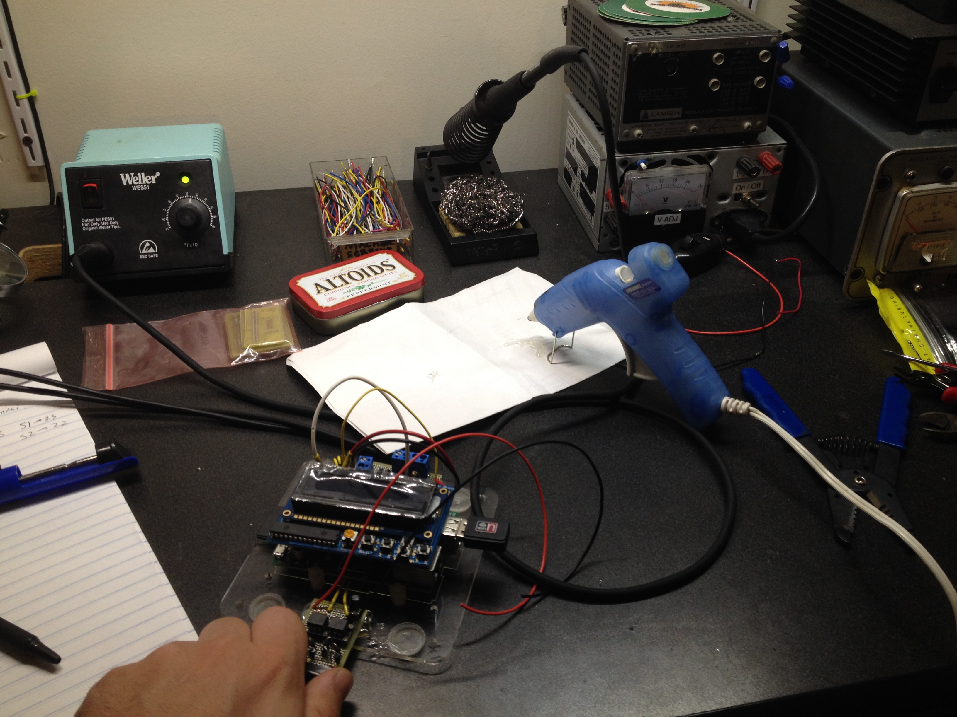
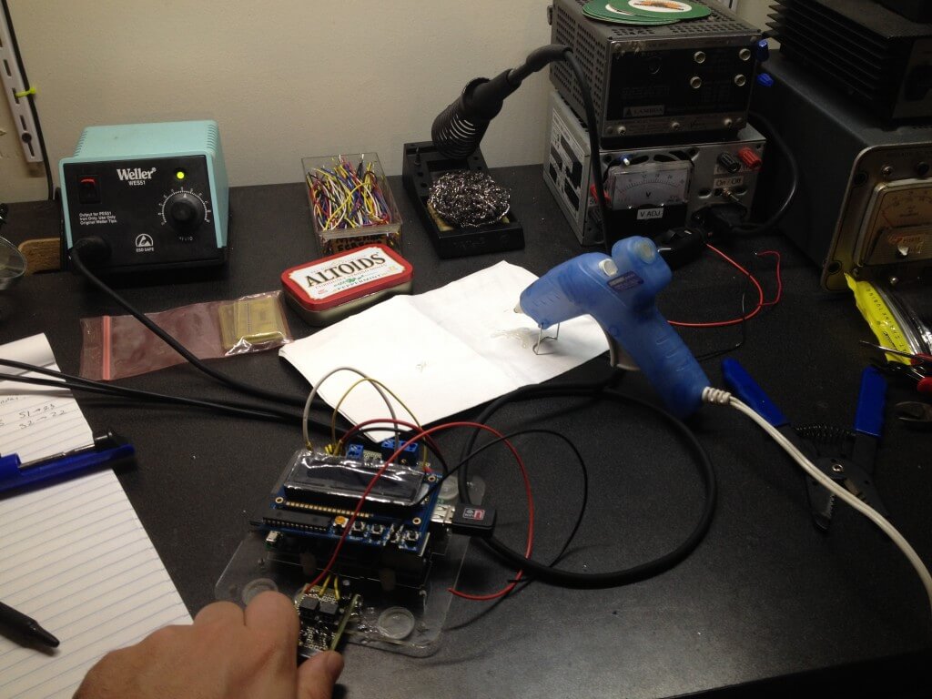
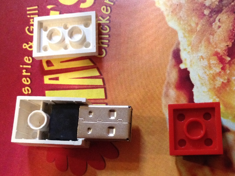
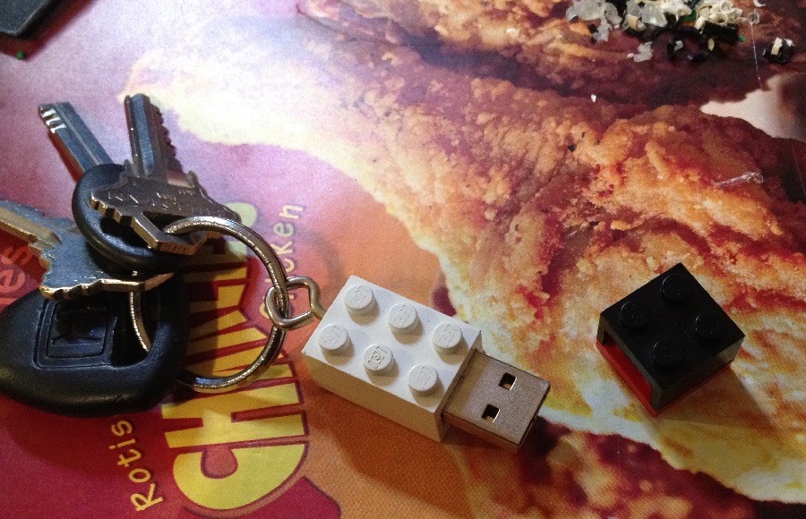
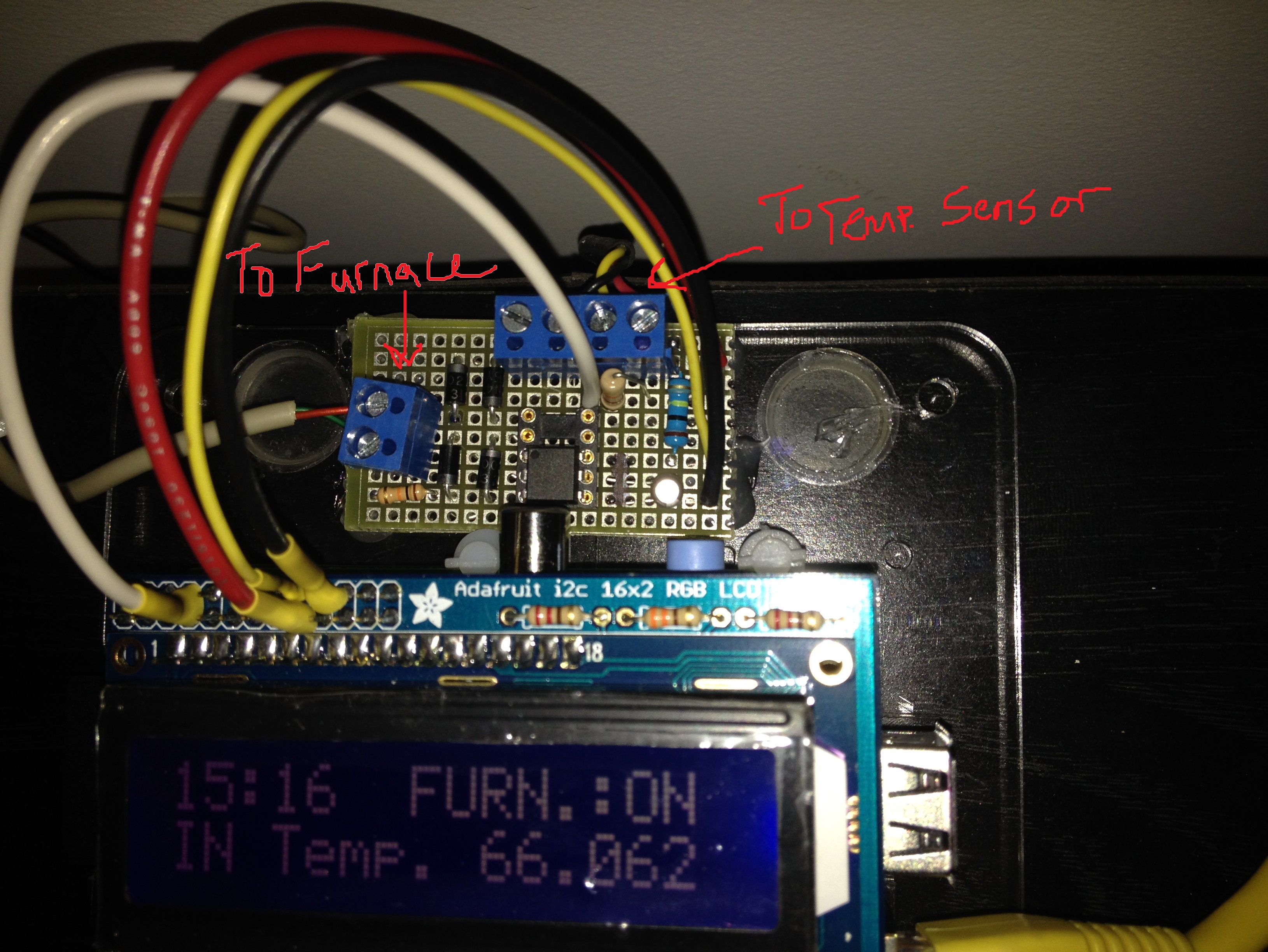
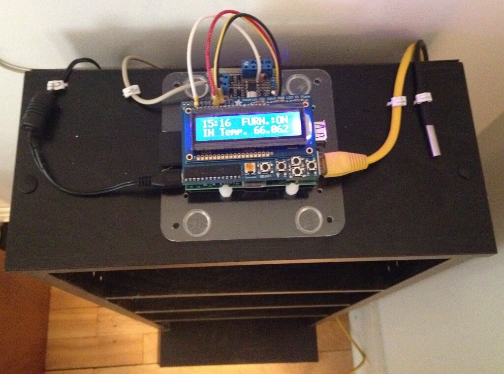
The last piece for this was an LCD screen.  I did some research and picked a product from Adafruit that has a 16X2 RGB LCD Screen and 5 buttons on a “shield” style board that plugs into the GPIO header on the pi.  I ordered one and when it came in, I soldered it together.

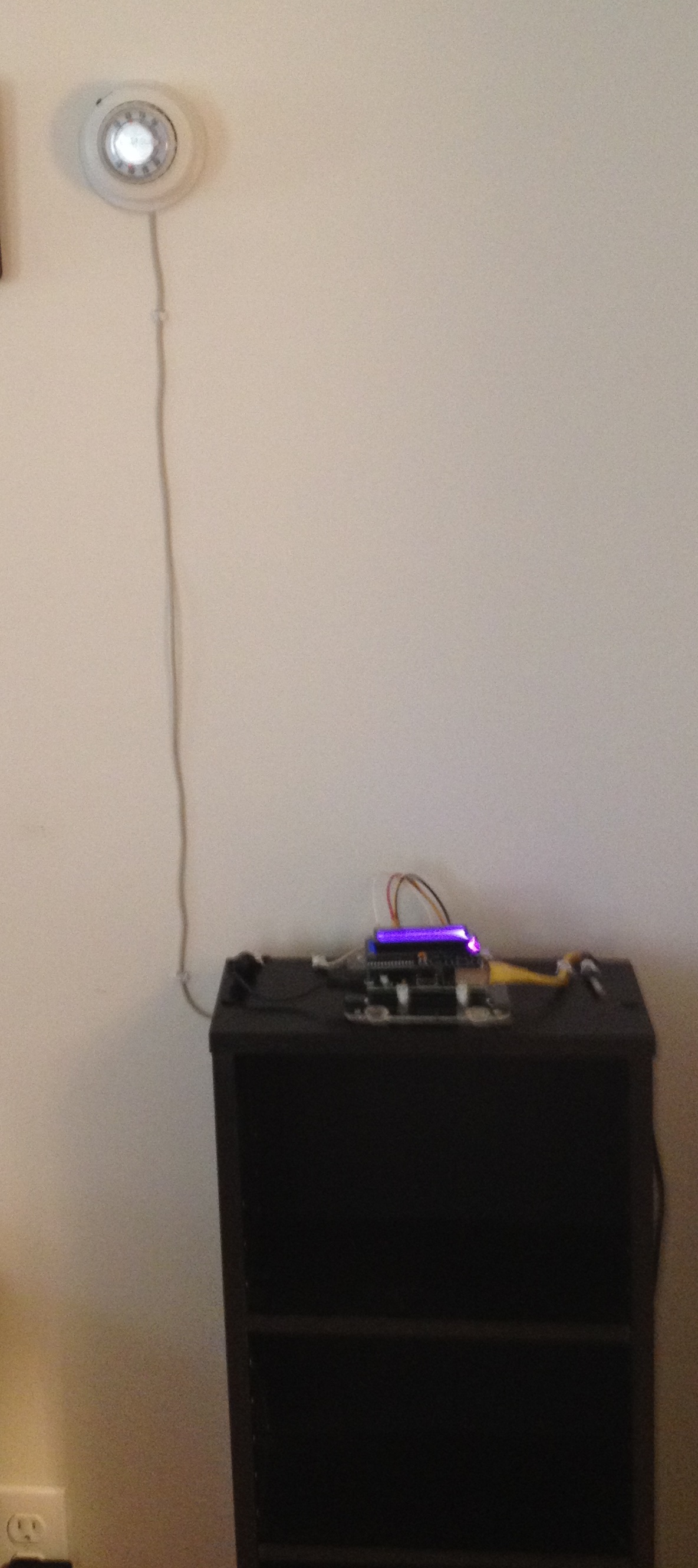
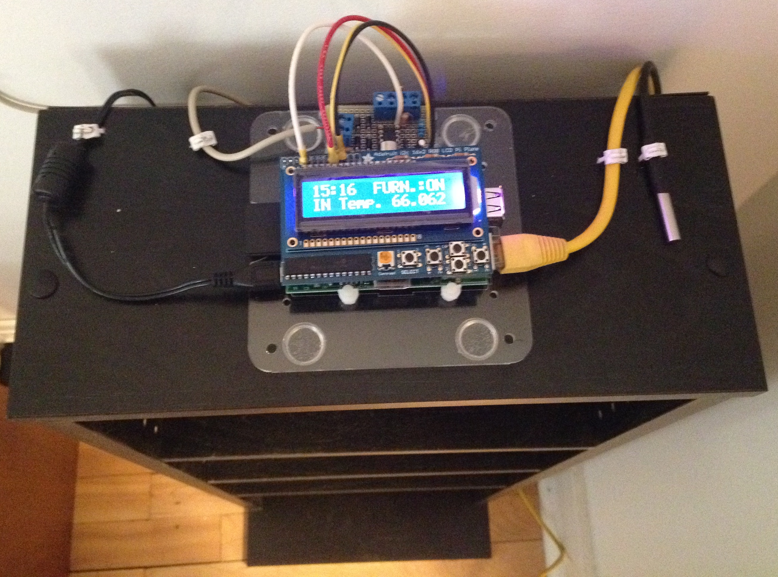
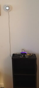
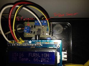
After much programming (That will be a future post), I had all the parts working.  So it was time to put the unit together.  I plugged the LCD screen into the pi, then soldered some wires to the backside of the header-pins on the LCD shield.  The other ends of the wires go to some proto-board where I built the schematics pictured above.  I then added a 2-conductor wire in parallel to the thermostat and connected the other end to the pi’s “furnace” input.  I wired up the Temperature sensor.  I mounted it all to a bookshelf and fired it up.

thermostat_pi proto-board temp-sensor pi_installed_edit

show_graph


CNC Sign

Jesse unveiled the finished product in a previous post, and it does look awesome.  Here are some photos and a simplified and incomplete account of how we got there.  Disclosure, this took place off-campus of Laboratory B as we do not currently have the tools on-site.

This sign was created by etching a sheet of acrylic and then edge-lightning the result.  The etching is basically a shallow cut that causes light in the material to reflect out.  The cutting was accomplished using a computer numerical controlled (CNC) milling-machine.

First, we started with a high-res version of the Laboratory B Lightning Bolt (credit to Brenton).  This was imported into a program called PartMaster and converted to a .dxf file.  From this CAD file, we asked the computer (nicely) to generate G-code.  G-code is what we needed to describe to the CNC machine how to move the cutting bit and etch the material.  The CNC machine is controlled by a program called Mach3 CNC.  This software reads text file containing the G-code and interfaces with the milling-machine to move the XY table and the drill head (Z) in order to accomplish the cut.

blogshot1 blogshot2

The milling-machine we used for this project was… a little too big.  We wanted to use the whole 10″ x 8″ sheet so we used the big machine, but since it’s not a router, it is normally used with R8 Collets…. the point is, the chuck we used to hold the etching bit was too short.  You can see in this next photos that we couldn’t reach the table and had to add some height to the mounting of the acrylic.  Once this was done, we “zeroed” the machine.  This is a process where we tell the Mach3 software what the location of the material to be cut is, so that it moves everything into the right place at the right time.  Then we hit “START” and watched!  Action shots follow, complete with my watching through my safety goggles.

blogshot3 blogshot4 blogshot5 blogshot6

Procrastination Success

I should have been grading lab reports, but instead I made this key holder with some Legos.  I screwed some picture frame hooks into a few full-height blocks (2×4, 2×3, 1×4) and attached a large base to the wall.  Put some key rings on the Legos, attach the Legos to the base, key holder.  My favorite part is that I can add whatever creation I want to the base plate as long as it can sit vertical, which is always true because it’s Legos.  This is a simple spaceship I put together in a few seconds.

keys

front left