Project: Laptop LCD

My sister has an old Gateway NV7802U. Not a bad machine, it has a 2.2GHz processor, 4 GB Ram, and a 500GB. Tiger Direct review. Last week, I was told there was a problem and I said I would take a look. Below, it is in its natural state.

Unfortunately, when it is powered up, it is obvious what the problem is. She stepped on it and broke the screen. I found a replacement screen for the Laptop model on ebay for $149.99 but I thought if I might open it up I could find the model of the screen and might find the screen directly for less money somewhere.

After some fairly difficult figuring out, I was able to pull the screen out. It was a little funny as there is a webcam in the cover just above the screen. There was also two screws in the bottom of the laptop that had to come out.


After taking it out, I turned the screen over to find the model. Voila! Here it is, a Samsung LTN173kT01-A01. You may notice that the screen (and the laptop, for that matter) was relatively recently made. “0935” is a date-code meaning 2009, week 35. This puts it late August of 2009.

Unfortunately, my plan hit a wall when I could only find this type of screen for more than $149.99. It turns out that the replacement for the Gateway that I found on Ebay is not this model, but instead an LG LP173WD1-TLA1 and the LG is $75.  It looks like the LG would fit, but I wanted to do some research to confirm. I can imagine that Gateway manufactured this laptop (and the rest during this run) with whatever parts they could get at the moment and this screen happened to be a Samsung. At other times, they might use the LG.

The screen came in. It was simple to install, with the hardest part being to remember where the screws go. Because of this I tried turning it on before adding the hardware, as can be seen below.

After I got it all put together it was fine. Hooray!

For the record, I bought the screen on Ebay. The supplier was in China, and the screen came from Shenzen, China via UPS. Total time on this project other than shipping time for the new screen was about 1 hour.

-KB1SVH

Project: Headphone volume control

I recently moved to a new cell phone, a Motorola Triumph.  One of the first  problems I encountered has to do with the media volume.  A little background: I listen to music at work almost constantly from the moment I sit down at 8:00am until I pack up everything between 5:00 and 7:00 pm.  I keep it low enough to hear other things going on around me and usually have only one ear in, but I need the background to keep me occupied and entertained.  I have been using my Motorola Droid and streaming radio over 3G from Verizon (using my old unlimited data plan).

With the Triumph, I had two problems.  The first and more easily fixable problem, the 3G coverage from the Sprint network does not cut it at work.  Heck, I barely have enough signal to make a phone call.  But the solution is simple, to use the wifi at work.  Second, and not as easily fixable, is that the volume from my earbuds at the lowest volume setting is WAY too loud.  Like, other people can hear them loud, not to mention that I can’t hear anything else.

I looked for some software solutions in the android market (Google Play Store, whatever) and found plenty of apps to adjust the volume, but none that could adjust finer than the 15 levels (+off) that android already supports.  So, I decided to fix it in hardware!

My plan, to make an in-line volume control that I could plug in at the phone then plug headphones into.  This would also be viable for any other devices using 3.5mm jacks (such as mp3 player into a stereo), although I don’t need it anywhere else right now.

I did a little research, and of course other people have done this.  Which is good for me, because it helped me find what size potentiometer I wanted to use as a volume knob.  I used this instructable to find that I wanted a 1K audio potentiometer.  Which basically means 1 knob controlling 2 pots, one for left channel and one for right channel.  There are only 5 pins because the pots share 1 rail, which is used as ground (the audio channels already share ground).

The parts I needed:

– 3.5mm Male Stereo Audio Jack
– 3.5mm Female Stereo Audio Jack
– Small gauge Stereo Audio wire
– 1Kohm Thumbwheel Audio Potentiometer for Volume Control

Now, the instructable recommends (correctly) that you harvest the parts for this from other things.  I had all of these things easily accessible immediately, except for the potentiometer.  I would normally go ahead and rummage through my (junk) electronics piles and find one.  But I was in a rush and going to dinner at a friends house the night I decided to do this.  So, while still at work I looked at the Radioshack website and found something close.  It is a 10K volume wheel.  I decided this would be close enough with 1K resistors across the pots in parallel, turning them into 909ohm potentiometers.

Here are some excerpted images from the instructables article.

Schematic
Wiring Diagram

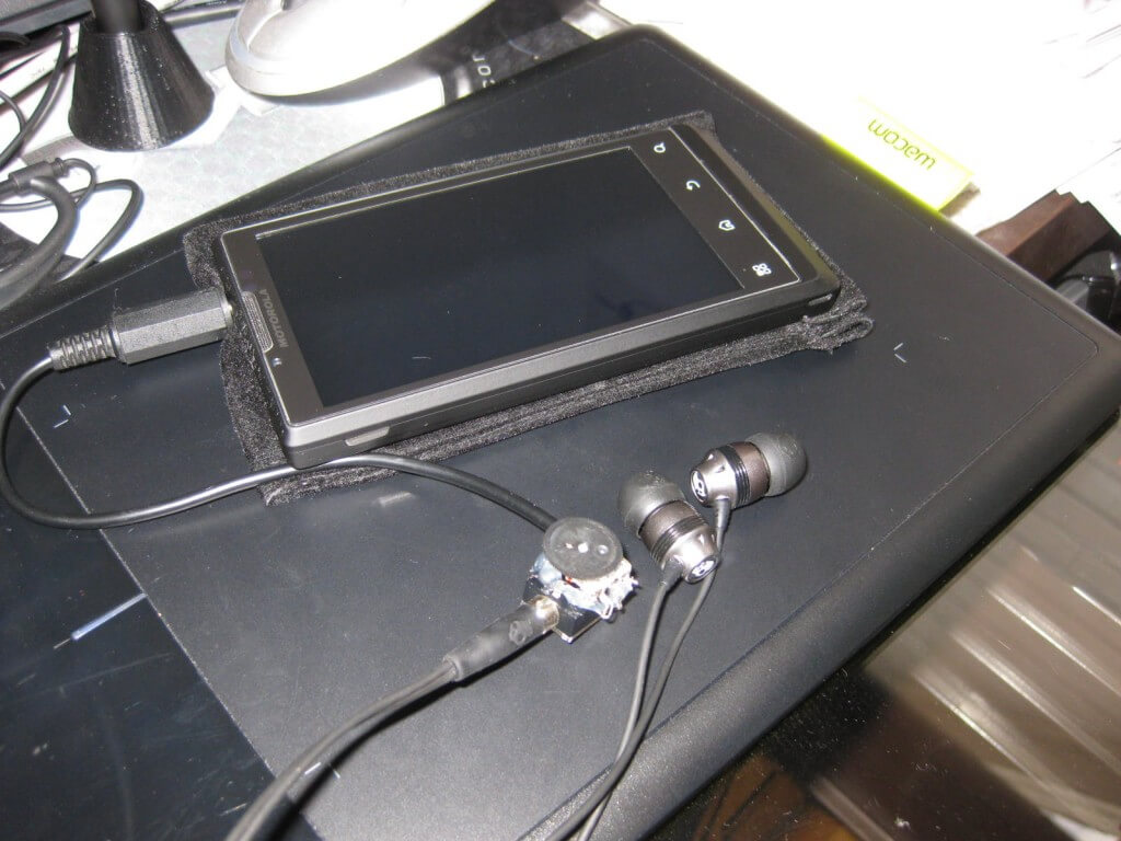
Again, my final product has a 10K potentiometer with 1K resistors in parallel.  You can’t see them below, but   they are there, under the wheel and above the headphone jack.  I used hot glue to hold it all together and add structural support when I plug and unplug headphones into it.

-KB1SVH